NEx 1 – NEx 4 A rotary and part-turn actuator
Rotary and part-turn actuators of the NEx series meet the requirements of Ex Zone 1 marking. The actuators have the following registered IECEx and ATEX certificate numbers: IECEx EPS 15.0061X and EPS 15 ATEX 1 044 X.
They are mainly used in industrial plants e.g. in machines operating in the chemical industry, in refineries, in fuel depots and in painting facilities.
The NEx is available with a synchronous motor as well as in a DC version (incl. BLDC) with a torque of up to 500 Nm. Featuring a high holding torque and self-adapting wide-range input power pack the programmable BLDC motor supports almost all positioning times and torques within a range of 2 Nm to 500 Nm.
The NEx is based on the extremely successful N series. That means it is possible to guarantee combination options with existing extensions such as supplementary gearboxes and linear units.
Boasting a wide variety of options, NEx offers the best possible solution for applications in process plant engineering subject to IECEx and ATEX regulations.
The design of the housing made of die-cast aluminium in combination with permanently lubricated gearing with sintered-bronze bearing bushes ensures their suitability for use in a harsh operating environment.
![[Translate to English:] NEx 1 – NEx 4 A Dreh- und Schwenkantrieb](/fileadmin/content/produkte/IECEx_ATEX%20/05_2019/Nex_1_4_600_650.png)
Housing
- Housing and hood are made of corrosion-resistant gravity die-cast aluminium
- Coating with silicone-free paint
- Colour RAL 7032 Pebble Grey
- The motor compartment is designed as a type “d” flameproof enclosure to DIN EN 60079-1
- Degree of protection IP66/67
- Options:
- Custom colours
Synchronous motor
- Single-phase AC synchronous motor with permanent magnets, reversible
- 230 V ± 10%, 50/60 Hz ± 5 %
- ON time 100% duty cycle on request
- Short start/stop times
- Insulation class B to VDE 0530
- Synchronous motors maintain speed and positioning time irrespective of the load
- Options:
- Custom voltages
- Custom frequencies
BLDC motor
- Brushless DC motor
- Constant positioning time thanks to electronic speed controller
- Wide-range voltage input 90 V AC … 264 V AC, 120 V DC … 370 V DC
- High holding torque when the operating voltage is applied
- Manufacturer configured start-up and brake ramp
- ON time 100% duty cycle
- Insulation class B to VDE 0530 DC motor
DC motor
- DC commutator motor
- Voltage 12 V DC or 24 V DC
- Insulation class E to VDE 0530
Gearbox
- Spur gearing with straight-toothed steel gears
- Rugged, maintenance-free
- Permanently lubricated gears
- Self-lubricating sintered bronze bearings
- Encapsulated version, operates in any position
Output shaft NEx 1 to NEx 4
- Diameter 14 mm, with 6 mm diameter cross-hole
- Options:
- Diameter 14 mm with feather key
- Diameter 12 mm with 5 mm diameter cross-hole
- Diameter 12 mm with feather key
- Input shaft with square socket WAF 14 mm (F05 DIN ISO 5211)
Electrical connection
- Connection by means of 1 m cable end or Ex “e” rated terminal box with spring-loaded terminals
- Customer-side wiring outside of the flameproof housing
- Electric anti-condensate heater
- Manual reset temperature switch 80 °C
Controller
- Open/close signal
- Options:
- Additional potential-free contacts
- eElectronic position controller ESR-N with Profibus and USB interface for synchronous motors
- Potentiometer 200Ω … 10 kΩ
- Blocking protection by monitoring changes to the actual value of the potentiometer (only in conjunction with position controller ESR-N)
Ambient temperature
- -20 °C to +60 °C
Angle of rotation limited by snap-action position off switch
- Two limit switches (standard)
- All travel-dependent switches actuated by infinitely adjustable control cams
- Changeover switches with silver-plated contacts
- Switch connections routed to terminals
- Switching capacity: max. 6 A, 250 V AC
- Options:
- Switches with gold-plated contacts
- Switches with positive-break contacts
- Additional auxiliary position switches on request
Position sensor for external position indication (optional)
- With potentiometer
- Conductive plastic potentiometer (standard) or wire-wound potentiometer (including TÜV approval)
- Multiturn potentiometer up to 10 turns
- Gearing makes it easier to adapt the electrical angle of rotation of the potentiometer to the desired angle of rotation of the actuator
- Special potentiometers with TÜV-approved form-fit attachment solution are available for electronic fuel/air ratio control
- With 4 ... 20mA transmitter
- Gearing makes it easier to adapt the electrical angle of rotation of the transmitter to the desired angle of rotation of the actuator
- With Hall sensor
- The wear-free absolute encoder that makes use of the Hall effect is particularly suitable for continuous operation in potentially explosive atmospheres
Manual operation (optional)
- The position of the input shaft and valves can be moved manually using a handwheel
- Disengaging the gear train and motor reduces the amount of force required
- Position switch-off settings are retained during manual operation
- The handwheel remains motionless during electrically powered operation
Options
- Other voltage/frequency
- Gear train disengages mechanically
- Handwheel
- Additional auxiliary position switches
- Custom control cams
- Electronic position controller ESR-N (in conjunction with synchronous motor)
- Position sensor
- Relay for switching several actuators in parallel
- Potentiometer
- Components to UL standard
Assembly
- Easily mounted thanks to stable angle bracket/ISO bracket
- No-fuss coupling to valve stem by means of:
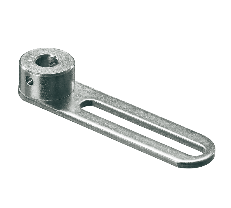
- Hand-operated lever coupling
- Lever arm, clamping lever, ball-and-socket joint, connecting rods, sprung connecting rods
- Flexible shaft coupling
- Rigid shaft coupling
Safety instructions
- In a potentially explosive area, ensure the device is isolated from the power supply before the hood of the flameproof encapsulated housing is opened by a specialist. The waiting time specified on the rating plate must always be observed!